GPS: Theory, Practice and Applications
Frederic G. Snider, R.P.G.
Introduction
Ever since people began to explore the world, one of the most difficult questions has always been "Where the heck am I?", probably followed closely by, "How do I get where I want to go and back again?" The answers to these questions led to the art and science of navigation. On land, navigation was based on reference to known locations. Over water, the problem was addressed using the sun and stars as references. Mapping and surveying had their own set of requirements for measuring distances and documenting position. The needs of navigation, mapping and surveying led to the development of compasses, transits, chronometers and a host of other equipment and techniques over the ages.These methods worked within certain boundaries. The sun and stars weren't always visible, and land explorers venturing into unknown territory soon ran out of familiar landmarks. Accurate surveying was a slow and laborious process.
After the second world war, it became obvious that we needed a solution to the problem of rapid and accurate absolute positioning. Over the next couple of decades, a number of projects and experiments were run. In the early 1970's, a bold experiment was proposed. A network of satellites, positioned thousands of miles above the earth, could provide rapid, accurate and absolute positioning anywhere. This vision became known as the Global Positioning System or GPS.
The GPS system belongs to the Department of Defense (DOD) and is officially known as the NAVSTAR System (Navigation Satellite Timing and Ranging). Its primary mission is to provide the U.S. Government and the Department of Defense the ability to accurately determine one's position at any point on the earth's surface, at any time of the day or night, and in any weather condition. Sounds simple, but it took a number of years and a commitment of over 12 billion dollars before the first GPS satellite was deployed. As originally envisioned, a minimum constellation of 24 satellites would be required to meet the objectives of the GPS program. More than 24 would provide redundancy and additional accuracy. Satellites would have a design life of 10 to 13 years, and would be replaced as needed. The full complement of 24 operational satellites was finally realized in 1994, more than 20 years after the system was originally proposed.
Although GPS was originally envisioned for military use, it soon became obvious that there would be numerous civilian applications as well. The first two major civilian applications were marine navigation and surveying. Since then, a myriad of applications have emerged, from personal positioning for scientific, commercial, and recreational uses, to truck fleet management, map-based navigation aids for automobiles and hand held computers, landing aids for aircraft, control of construction and agricultural machinery and, in the near future, reporting of exact cell-phone locations for emergency response purposes. As with many technologies, the uses of GPS extend far beyond what the original designers envisioned. As receivers have shrunk in size and weight and costs continue to drop, the number of users and applications has grown rapidly.
The U.S. has not been alone in pursuing GPS. Although the U.S. makes our GPS system available for free to anyone in the world, other countries have wanted their own, independent systems. The Russian Federation deployed a system known as GLOSNASS, which is also available for civilian use. Europe is currently debating developing its own system.
How Accurate is GPS?
This is probably the most frequently asked question posed by new and potential GPS users. In practice, we have to turn this question around and ask "How much accuracy do you need?". For example, for a hiker in the woods or a soldier in the field, a position within about 10 meters (30 feet) would usually be considered accurate enough. For a ship in coastal waters, accuracy on the order of about 5 meters (15 feet) is generally desirable. For geodetic land surveying, however, accuracy requirements are 1 centimeter (0.4 inches) or less. GPS can be used to achieve all these accuracies. For each required level of accuracy, receiver characteristics and the measurement techniques employed are different. Accuracy also depends on satellite configuration, nearby topography, distribution of buildings and trees, and even time of day. Techniques and factors affecting accuracy are covered later in this course.Components of the GPS System
There are 3 main components to the GPS system. These components are known as Segments, as follows:
These three segments are illustrated schematically below.
Each of these segments is described in the following sections.
Space Segment
The space segment consists of the GPS satellites. Much of the GPS literature refers to the satellites as "space vehicles" or simply, SV's. The arrangement of GPS satellites in space is called their constellation. The minimum constellation to meet the objectives of the DOD is 24 operational satellites.The orbit altitude was selected so that each satellite repeats the same track over any point on earth approximately once every 24 hours. One orbit takes a little less than 12 hours. There are six orbital planes, with nominally four satellites per orbital plane. The planes are equally spaced 60 degrees apart inclined at about 55 degrees to the equator. The configuration was optimized to provide the best coverage between about 75 degrees north latitude and 75 degrees south latitude. This constellation provides the user with between five and eight satellites visible from most any point on earth at any time.
The satellite orbits are approximately 20,200 kilometers (12,000 miles) above the earth surface. The satellites travel at about 12,000 km/hour (7,000 miles per hour). Each satellite is solar powered with battery backup, and contains radio receivers and transmitters, one or more atomic clocks, small thrusters used for course corrections, special antennas, and, of course, computer equipment. The antennas on the satellites are designed to allow GPS signals to be received anywhere from the earth's surface to about 5,000 km (3,000 miles) into space. This "service volume" not only meets all civilian needs, but also provides the military with satellite tracking and missile guidance capabilities.
The first GPS satellite was deployed in February of 1978. By 1994, a total of 24 operational satellites were in place. Replacements and upgraded satellites have been launched on a regular basis. As of early 2001, a total of 43 satellites had been launched, and the operational constellation consists of 28 satellites. The number of satellites reported in various books, articles and Internet resources varies considerably, reflecting the date that the work was prepared.
Control Segment
The U.S. Military operates the control segment. There are five control stations around the world, four unmanned stations near the equator and one Master Control Station in Colorado, as shown on the following figure.
The four unmanned stations constantly receive data from satellites and also track the exact position of the satellites. This information is periodically sent to the Master Station, which combines the data and establishes correction factors. This information is then uplinked once or twice a day back to the satellites from the Master Station and three of the unmanned stations. As part of this process, the atomic clocks on the satellites can be updated if necessary. Thrusters on the satellites may also be fired to adjust their positions in their orbits and maintain them in their proper slots. Thrusters are usually fired once a year to make up for slowing orbits and drift of the satellites outside their designated positions.
User Segment
The user segment consists of all the users of the GPS signals. This includes both civilian and military users. It is important to note that GPS receivers do not send any signals back to the GPS satellites. Therefore, it is not possible to track the position of a receiver using GPS satellites. The satellites merely transmit their signals blindly throughout the service volume. In this way, the number of potential users at any one time is unlimited, and there is no interference between users.As opposed to the space and control segments, which are maintained by the U.S. government, the user segment is served by many commercial companies who manufacture and sell GPS receiver hardware, software and services. Anyone in the world can make and market GPS receiver equipment. There are no licenses, user fees, or any other restrictions. Allowing the private sector to design and manufacture receiver equipment has resulted in a continual reduction in size and cost of GPS receivers, at the same time increasing ease of use, features and potential applications.
GPS Signal Characteristics
Each GPS satellite transmits low power (20- to 50-watt) radio signals. Consider the difference in the strength at the ground surface of a 50-watt radio signal coming from a satellite 12,000 miles out in space and your local FM radio station, which may be transmitting 100,000 watts of power from the top of a 200-foot antenna just a few miles away.Each satellite transmits information at two carrier frequencies, called L1 and L2. The carriers L1 and L2 are pure radio waves and in themselves contain no information. This is the same principle as the carriers used in radio broadcasts. When you tune your radio to, say 101.1 FM, you are receiving a pure signal at a base frequency of 101.1 megahertz (million cycles per second). The music you want to listen to is superimposed on this carrier wave by slightly varying the base frequency synchronized with the music. This transmission technique is called frequency modulation, or FM. Another technique is changing the amplitude of the base frequency synchronized with the music. This technique is called amplitude modulation, or AM. Thus use of the terms FM and AM radio.
Data from the GPS satellites is all digital, which means it is represented as long strings of 1's and 0's. In many ways, this information is much simpler to superimpose on the carrier frequency than music, thus providing a more reliable and error-free signal. This type of data transmission is also less susceptible to jamming.
The GPS signals travel along "line of sight" meaning that satellites must be in view to receive signals. The signals will pass through clouds, glass and plastic, but not through most solid objects, such as buildings or rock and soil. GPS signals will not pass through water. Dense foliage can also attenuate the signal. Therefore GPS works best in open areas with clear view of the sky.
GPS Data
Three types of data are superimposed onto the L1 and L2 carrier frequencies. These data types are called the Navigation Message, the C/A (coarse acquisition) Positioning Code and the P (precision) Positioning Code. The Navigation Message and the C/A Code are accessible to everyone and are called the Standard Positioning Service (SPS). Civilian users worldwide can use SPS without charge or restriction.The P-Code data is encrypted and is available only to users with appropriate cryptographic systems and keys, and is termed the Precise Positioning Service (PPS). PPS is available only to the U.S. and allied military, certain U.S. government agencies and selected civil users specifically approved by the U.S. government. The P-Code data provides these users with increased positional accuracy. The encryption of the P-Code data is termed "anti-spoofing" or A/S.
Determining Position using GPS
The GPS system determines your location using a surveying technique known as "trilateration". This refers to using distances from several known locations to compute the coordinates of an unknown location. In this case the "known locations" are the positions of GPS satellites. Therefore, in order for your GPS receiver to calculate your position, it needs the location of each visible GPS satellite. The distance to these satellites is calculated using the time it takes the GPS radio signal to travel from each visible satellite to your receiver.How accurate must this information be? If the satellite position was known to the nearest mile, then your position calculation could only be determined to the nearest mile. Accurate satellite location is therefore critical to accurate positioning. The GPS system is designed to track the position of each satellite to within about 1 meter (3 feet) of its actual position. Imagine the technology behind identifying the position of a satellite 12,000 miles up, traveling at 7,000 miles per hour within 3 feet!
With respect to measuring the travel time for the GPS signals to reach you, if you were off by even 1/1000 of a second (1 millisecond), your positional fix would be off by more than 300 kilometers (186 miles). To achieve 1-meter (3 feet) accuracy, the travel time measurement must be accurate to within 3 nanoseconds (3 billionths of a second!).
Therefore, the determination of accurate satellite position and accurate travel time of signals to your receiver are the essential core of GPS technology. So before we explain how your position is actually calculated, it is valuable to discuss how satellite position is determined and how travel time is measured.
Determining Satellite Position
The path of each orbiting GPS satellite could theoretically be predicted using Kepler's three laws of planetary motion which he published in 1609 and 1619. The predicted path is based on the assumptions that the only force acting on the satellite is the gravitational pull of the earth and that the earth is a perfect sphere of uniform density. In reality, these assumptions are not valid. First, the earth is not a perfect sphere (it bulges along the equator and flattens at the poles). Second, it is not of uniform density. Third, other heavenly bodies (particularly the moon and the sun) have their own gravity fields, which also act on the satellites.Other complications are introduced by the fact that the satellites are not traveling in a perfect vacuum, so there is very slight atmospheric drag. More importantly, the satellites experience the impact of photons of light emitted by the sun both directly and reflected off the earth and moon. This is termed solar radiation pressure and is a function of the satellite's size and orientation, distance from the sun, and other factors. Solar radiation pressure slows down the satellites headed towards the sun and accelerates satellites headed away from the sun. For GPS satellites, this effect is virtually impossible to accurately model and represents the largest unmeasurable source of error.
Since it is not possible to accurately predict the location of each GPS satellite, their actual locations must be measured periodically. The four unmanned monitoring stations in the control segment are used, in part, to track all the satellites and periodically determine their actual position. The error in the location is generally less than 1 meter (3 feet).
The location information is periodically sent from the unmanned tracking stations to the Master Station in Colorado where a master list of satellite locations is maintained. However, the satellite location data is needed by all GPS users. Therefore, the latest information is periodically uplinked to the individual satellites so that it will be available to all users.
The location information is broken into two parts called the "almanac" and the "ephemeris". These two classes of location information are described in the following sections.
Almanac Information
Almanac data describe the approximate satellite orbital data over extended periods of time, which in some cases can be useful for several months or more. Each satellite contains all the almanac data for the entire constellation. Therefore, a GPS receiver need only download the almanac data from one satellite to calculate the approximate location of all satellites in the system.The almanac information is transmitted every 12.5 minutes and takes 12.5 minutes to download. Therefore, when a receiver is turned on and updated almanac data is required, at least 12.5 minutes of download time would be required before accurate fixes could be determined. One GPS receiver manufacturer calls this the "Search the Sky" startup mode. Other manufactures call it the "warm up" mode. No matter what brand equipment you use, it will take at least 12.5 minutes to download the almanac data. All GPS receivers store the almanac data in memory, so that once the almanac data is stored once, it need not be downloaded again until an extended period of time has passed and the data becomes "stale". The almanac data also becomes stale if you move the receiver to another location more than several hundred kilometers away.
Ephemeris Information
The ephemeris information contains the precise location of each satellite and the parameters needed to predict its position for the near future. In contrast to the almanac data, each satellite transmits only its own ephemeris data. Therefore the GPS receiver must gather ephemeris data from each satellite in view. Each satellite transmits ephemeris data every 30 seconds, so GPS receivers have ample opportunities to gather this essential information. It takes 12 seconds to download the ephemeris data from one satellite.The ephemeris data is considered valid or "fresh" for up to 4 to 6 hours. As part of the ephemeris data stream, each satellite transmits an indication of how long its data will be valid. The GPS receiver is responsible for tracking this information and updating its internal copy of the ephemeris data when necessary. Some manufacturers choose to download the ephemeris data on a regular schedule, for example every 30 or 60 minutes, rather than tracking the freshness data from the satellite. In any case, fresh ephemeris data is critical for accurate positioning. Most GPS receivers will indicate when they are downloading ephemeris data instead of calculating position, so the user will not think the receiver has malfunctioned or quit working.
Measurement of Travel Time
Once a GPS receiver has fresh almanac and ephemeris data, it knows the actual locations of the visible GPS satellites. But this information is of no value unless the receiver also knows the distance to each of these satellites. The distance is determined by measuring how long it takes for the radio signals to reach the receiver from each visible satellite. The technique used is best explained by example. The satellites each have highly accurate atomic clocks, and the receivers have less accurate crystal controlled clocks.
Supposing that the system is set up so that at exactly 1 p.m. each day, a satellite and your receiver start to play Beethoven's Fifth Symphony. The satellite transmits the Fifth Symphony on radio waves that travel at the speed of light. Your receiver receives the signal and compares it to the version it is playing itself. If both clocks were perfectly synchronized and accurate, the symphony from the satellite would be slightly behind your receiver version, since it took some time for the signal to reach you. The amount of time you need to shift your version back to be in sync with the satellite version would be the travel time from the satellite to you. Knowing the speed of light (about 186,000 miles per second or 300,000 kilometers per second) makes it easy to compute the distance to the satellite using the following formula:
Distance = travel time x speed of light
This assumes, however, that your receiver started playing the Fifth Symphony at exactly 1 p.m. Note that if you were off by even 1 millisecond (1/1000 of a second), your distance calculation would be off by 300 kilometers (186 miles). Since the clock in your receiver is not sufficiently accurate, we still can not accurately compute the real distance to the satellite.The key to resolving this problem is receiving several symphonies at the same time from multiple satellites. These symphonies are the digital codes transmitted by the satellites 1,000 times every second. With multiple satellites and a unique symphony from each one, the GPS receiver can correct for errors in its own clock and determine actual travel times.
Calculating Your Location
Once we know the positions of visible GPS satellites and distances to those satellites from the receiver, we can begin to calculate your position. This is best explained one step at a time. For simplicity, the following explanation is shown in two dimensions. Say, for example, we know the distance "R" from one satellite to our receiver. In two dimensions, we could be anywhere on a circle of radius R, as shown on the following figure.
If we have ranges from two satellites, then we draw two circles and see where they intersect. In the example below, the receiver could be at point A or point B.
This is still not good enough. If we add one more satellite and one more range, then we can determine a unique solution, as shown on the following figure.
This is the ideal case. In reality, there are errors in the ranges from each satellite due to a number of factors. So we rarely get a single point of intersection. In fact, since a single point almost never happens when ranges are first calculated, the initial ranges are called "pseudo-ranges". The following figure illustrates the usual situation when the pseudo-ranges are plotted.
Unless the three pseudo-ranges are exact, the three arcs will not intersect at a common point. The area in yellow on the figure is called the "triangle of error", within which the final solution lies (X). By making small adjustments to its internal clock and applying various error corrections, the GPS receiver tries to minimize the size of this triangle and determine its final position.
This explanation oversimplifies the problem, since we are really working with a three-dimensional position. In mathematical terms, we have four unknowns: latitude, longitude, altitude and time. In order to solve for four unknowns, we need four equations. This translates to a need for a minimum of four satellites for a unique solution. More than four satellites allow for more accurate positioning. With four satellites or more, we are not only able to locate ourselves, but we can calibrate our receiver's clock to the same accuracy as the atomic clocks on the satellites!
Sources of Error
The main sources of error in the GPS system are as follows:
In the table, the error term is specified as Net RMS error. RMS stands for "root-mean square" and is a statistical measure. It means that approximately 63% of the calculated positions will be less than the error specified. Note that this means that approximately 37% of the positions will be greater than this error. In practice, the position error may be very large for a small percentage of the time.
Note that the Final RMS error of 40 meters assumes that all the error sources are contributing their typical or maximum value and in the same direction. This scenario overestimates the error since some errors may actually offset or cancel each other. In practice, the typical error is generally on the order of 10 meters (30 feet) or less in mid-latitudes.
Each of the sources of error is described in more detail below.
Atmospheric Effects in the Ionosphere and Troposphere
The GPS literature divides the earth's atmosphere into two layers: the troposphere and the ionosphere. Defined this way, the troposphere includes the stratosphere and the mesosphere and extends from the ground surface to about 80 kilometers (50 miles) up. This zone contains about 99.99% of our atmosphere. The ionosphere extends from the top of the troposphere to about 1000 kilometers (600 miles) above the earth's surface. It is called the ionosphere because solar and cosmic radiation strips electrons from molecules in this zone and ionizes the gases.The speed of light decreases in the troposphere and ionosphere, such that the calculated distance to the satellite is longer than the actual distance. Within the ionosphere, the extent to which the speed is reduced is dependent on the density of electrons along the signal path. The density of electrons is dependent on the geomagnetic latitude of the receiver, the time of day, and the elevation of the satellite (height above the horizon). Significantly larger delays occur for signals from low-elevation satellites since they travel through a greater section of the ionosphere. Errors peak during the day and subside at night due to the effects of solar radiation. Errors are also larger near the geomagnetic equator and near the geomagnetic poles (magnetic north and south).
All GPS receivers contain a mathematical model of the ionosphere. As part of the Navigation Message, GPS satellites transmit eight parameters to plug into this model. These parameters are updated as often as once or twice per day as data is compiled and processed at the Master Station.
The GPS receiver uses these parameters plus factors based on time of day and elevation of the satellite above the horizon to calculate an ionosphere correction factor for each satellite. However, since the model parameters sent by the satellite are based on a composite of the data collected from a number of satellites and ground stations, it can only be considered an "average" representation of the ionosphere at any given time. Therefore, GPS specifications state that the model parameters allow an estimate only within 50% of the true error. This fact results in location errors ranging from 5 meters at night to 30 meters during the day for low elevation satellites, and 3 to 5 meters for high elevation satellites at mid latitudes. The value of 10 meters (30 feet) was included in the table above as representative on a worldwide basis. Effects of the troposphere are small compared to those of the ionosphere, and error rarely exceeds 1 meter (3 feet).
Higher-end commercial receivers take advantage of the fact that the effect of the ionosphere is dependent on the frequency of the radio wave passing through it. The ionosphere error can therefore be nearly eliminated by using both the L1 and L2 frequencies transmitted by the satellites. This correction relies only on the carrier waves themselves and not the data contained in them. Therefore, these receivers can take advantage of the L2 frequency for this correction without having to decrypt the L2 positional data. This approach is called Dual Frequency Correction. Its primary advantage is that it directly measures the effect of the ionosphere along the signal path, and doesn't use the "average" model broadcast by the satellites.
Satellite Clock Synchronization Error
For perfect range calculations, the clocks on all satellites would be exactly synchronized. In reality, they are all within about 3 nanoseconds (3 billionths of a second) of each other. Although this is an astoundingly small number, it still translates into an error in position of about 1 meter (3 feet), since the speed of light is so fast.Electronic Noise
Electronic noise on the signal and within the receiver components can add additional error to the calculated position. Receiver noise is dependent on the quality and design of the receiver, interference from other radio signal sources, temperature and other variables. Error from electronic noise can be as high as about 2 meters (6 feet).Multipath Error
Multipath error is caused by the GPS signal reflecting off a surface or object before being detected by the receiver antenna. In extreme cases, this error can be as high as 15 to 20 meters. Studies have shown that large water surfaces are most conducive to reflecting the GPS signal and creating large multipath errors. Sandy soil is the least susceptible. Buildings or large rock faces can also be a source of multipath error, as shown on the following figure.
Multipath errors can be addressed in software, where special algorithms in the receiver attempt to identify and reject the multipath signal and lock on to the actual, direct signal. Such algorithms can usually reduce the potential multipath error to 0.5 meters or less.
Multipath errors can also be minimized by use of special antennas that include a grounded metallic disk about 2 feet in diameter or concentric metallic rings around the antenna to trap indirect signals. The use of grounded disk and ring antennas is usually reserved for high-accuracy surveying applications where error in the range of 1 centimeter (0.4 inches) or less is required. Such antennas are typically mounted on a tripod for stability.
Uncertainty in Satellite Position (Ephemeris Error)
As described earlier in this course, the accuracy of satellite position is about 1 meter (3 feet). This uncertainty in position can introduce errors of similar magnitude in the final position calculation.Intentional Degradation
Originally the military introduced random errors intentionally to keep military adversaries from using accurate GPS data. The errors included intentionally incorrect data as to the exact location of the satellites and/or changing the satellite clock frequencies.This intentional degradation in accuracy is termed Selective Availability or S/A. The degradation reduced civilian accuracy levels to a maximum of about +/- 100 meters horizontally. The degradation affected all civilian users of GPS. For example, if you were sitting in your boat tied to the dock, you would see large random changes in your GPS readout of speed, position and heading, even though you were not moving.
Selective Availability was eliminated on May 2, 2000, and has not been re-instated to date, despite the events of 9/11/2001. The Department of Defense has instead upgraded GPS technology to localize the control systems and to deny GPS signals to selected areas.
Satellite Geometry
The effect of satellite geometry is quantified in the measure called Dilution of Precision, or DOP. The following figure illustrates the effect of satellite geometry on precision.
On the left, the position of the satellites results in a small angle between the signals reaching the receiver. This adds uncertainty in the position calculations. On the right, the position of the satellites results in a 90-degree angle between the signals. This configuration minimizes the error in position calculations.
The best way to minimize the effects of DOP is to observe as many satellites as possible. However, it should be noted that for satellites that are low on the horizon, the travel time through the ionosphere is much longer and atmospheric errors are magnified. Therefore, it is generally considered best to ignore any satellites below about 15 degrees above the horizon. This angle is termed the "threshold" and can usually be set on your receiver.
Different types of Dilution of Precision may be reported on a given brand of receiver, as listed below. Each of these is a component of the total DOP.
GDOP is applied directly to the accuracy determined from all other error sources. For example, if your accuracy is computed as +/- 2 meters based on clock and other errors, and the GDOP is 6, your final accuracy will be +/- 12 meters (2 X 6). This is why favorable satellite geometry is a key factor in the accuracy of positioning. In most mid-latitudes, a GDOP of 4 can usually be attained, as indicated on the error table (Table 1).
Improving Accuracy - Differential GPS
Location accuracy can be significantly improved using a technique called Differential GPS or DGPS. The DGPS technique is based on using at least two GPS receivers. One receiver is located at a fixed position which has been accurately located using traditional land surveying techniques. This receiver is known as the base station, and also contains a computer. The remaining receivers are roving, and are used for the surveying or navigation activity.The base station takes GPS readings continuously and calculates its "position" based on the GPS data. The computer then compares the receiver position based on the GPS data to the actual receiver location based on the accurate land survey. The difference between the GPS calculated "position" and the real position of the receiver is the error in the GPS for that particular reading. Each reading is also time-stamped, so we know for what time of day the errors are valid.
Low-end differential GPS systems are capable of sub-meter accuracy, especially if the base station is within a few miles to tens of miles of the roving receivers and both the base station and roving receivers see the same set of GPS satellites. High-end DGPS equipment is capable of sub-centimeter accuracy.
Two types of Differential GPS systems exist: Post-processing DGPS and Real-time DGPS. In Post-processing DGPS, the base station records the time of each reading and the associated correction factors. At the end of the day, the positional data from the roving GPS receivers are downloaded to the computer and each reading is corrected (based on the time the reading was taken). This approach is sufficient for surveying or other activities where the exact position of the roving receivers is not important at the time of the readings.
However, the post-processing approach is of little use for real-time navigation or positioning tasks, such as guiding aircraft to a runway. Real-time DGPS includes a radio transmitter at the base station. After each GPS reading, the base station quickly calculates the error and transmits it via radio signals to the roving receivers. The roving receivers need to be equipped with an appropriate radio receiver and the computational ability to add the correction factors to their own GPS readings in real time. The location displayed on the GPS receiver, then, would have the errors factored out.
In practice, post-processing is still used for surveying tasks, as processing all the data at the end of the day allows for sophisticated statistical analysis that improves accuracy.
The following figure illustrates the Real-time DGPS configuration. Note that only one satellite is shown. In reality, the base station must receive signals from all the satellites visible to the roving receiver.
For the highest accuracy in a local area, setting up a base station and using DGPS is the best approach. However, the U.S. Government realized the benefit of setting up permanent DGPS base stations and radios transmitters, especially along coastal areas and around airports. The installation of permanent DGPS base stations and making the correction signals available for free or by subscription is known as GPS Augmentation. Three augmentation systems, Beacon, WAAS and LAAS have been developed by the U.S. Government, as described in the following sections.
Beacon
The U.S. Coast Guard operates a network of 76 base stations, particularly around popular harbors and waterways. The correction information is transmitted via ground-based radio beacons. The published accuracy specification for the beacon system is 10 meters (30 feet). Most GPS equipment manufacturers have receivers that receive this free beacon data. This capability will be noted in the receiver's specifications. In addition to the U.S. system, there are about 124 beacons operating in other parts of the world.WAAS - Wide Area Augmentation System
The Federal Aviation Administration (FAA) operates a network of about 25 ground reference stations covering the entire U.S. and parts of Canada and Mexico. Each of these stations has been precisely surveyed and each contains a GPS receiver. All of the ground stations relay the error correction information to the wide-area master station (WMS). The WMS calculates an error correction algorithm and assesses the integrity of the GPS system. This information is uplinked to a geosynchronous communications satellite on a regular basis. (A geosynchronous satellite maintains its position relative to the ground. These are also known as geo-stationary satellites.) The error correction message is then broadcast from the geo-stationary satellite to receivers on board aircraft or on the ground.The correction signal can be accessed for free by any WAAS-enabled receiver. A number of commercially available receivers are WAAS enabled and can use the data from the geo-stationary satellites for additional error correction. According to the FAA, WAAS improves basic GPS accuracy to approximately 7 meters vertically and horizontally. At least one commercial vendor claims accuracy of 3-5 meters horizontally and 3-7 meters vertically using WAAS corrections. The WAAS satellite data also provides important integrity information about the entire GPS constellation, which can be used to provide the user with an additional level of confidence in the positional calculations.
LAAS - Local Area Augmentation System
The FAA is also implementing an augmentation to GPS that focuses its service on airports, including the area within about 30 to 50 kilometers (20 to 30 miles) of the airport center. The system uses several precisely located base stations at or near the airport to calculate the correction factor for positional data obtained from GPS. The correction message is broadcast via a very high frequency (VHF) radio link and can be received by any aircraft with an appropriate receiver. This correction message is applied by the GPS receiver on-board the aircraft. Accuracy is claimed to be sub-meter for both position and altitude. The goal of LAAS is to provide extremely high accuracy, high availability and high integrity to approaching and landing aircraft. Eventually, this system may provide sufficient accuracy that aircraft could land safely in zero visibility.Other Augmentation Systems
The private sector has also gotten into the DGPS augmentation business. Under commercial systems, users subscribe to a private augmentation network and receive the correction factors over FM radio or satellite links. The coverage areas and accuracy levels provided are variable. At least one commercial service advertises sub-meter positioning accuracy over most land areas of the world, based on a series of 90 base stations and transmission of correction data via commercial geo-stationary communications satellites. Users subscribe to the service based on the service area(s) they desire.There has also been some recent experimentation using the Internet to distribute correction data. This technique is currently useful for Post-processing DGPS surveys, where real-time correction is not needed. However, as broadband and wireless internet access improves, this may provide another correction delivery option for Real-time DGPS.
Real-Time Correction of Multiple Receivers - Inverse DGPS
Suppose you are interested in accurately tracking where a number of vehicles are and how fast they are moving using GPS in real-time, and you want to monitor all of them from a central location (for example, for a fleet of delivery or service trucks). Each vehicle would need a GPS receiver. That would tell the vehicle where it is, but not you. Therefore, each vehicle must transmit its own positional information, usually by radio, back to the home office. For accurate location and speed determination, you decide to use Differential GPS. To equip each vehicle with DGPS capability requires more equipment and is expensive. The better approach is to have one DGPS station at the home office, and use this single correction factor for all the data coming back from the vehicles. This technique is called Inverse DGPS.Inverse DGPS is applicable whenever there are multiple mobile receivers and the receivers themselves don't need differential GPS accuracy. This approach can be used for accurately tracking vehicles, weather balloons, semi-autonomous robots, or even real-time surveying of pre-defined points. Several companies offer inverse DGPS for public bus systems and even school buses, so that central dispatch always knows the status of the transportation system.
Applications of GPS Technology
GPS applications are continually being developed. With the recent development of software and hardware techniques to routinely obtain sub-centimeter accuracy even while receivers are moving, a host of new applications became possible. The following sections present a sampling of GPS applications in the fields of recreation, public health and safety, environmental monitoring, fleet management, engineering and construction, agriculture, the geosciences, marine navigation, military applications, and power generation and distribution.Recreation on Land, at Sea and in the Air
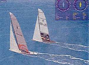
As the price of hand-held GPS receivers has dropped, the number of recreational users has increased dramatically. Recreational uses include boating, hiking, biking, four-wheeling, snow-mobiling, cross-country skiing, hot air ballooning, and private aviation. Automobile manufacturers and others offer moving-map displays guided by GPS for locating specific addresses. Some models provide voice prompts ("quick, hang a left, now!") as well as location of nearby services (gas, food, lodging) and recreational sites. Small GPS receivers can also be plugged into a laptop computer or personal digital assistant to create a portable navigation system. Detailed street atlases can be downloaded from CD's or the web for real-time moving displays.A unique example of GPS use at sea involved the posting of real time GPS positioning on the Internet during the 2003 America's Cup sailing race. With a huge racecourse and few markers on the water, judging the distance between yachts is difficult. Because sailboats must tack to reach the destination buoy, and because a change in wind direction of a few degrees can propel a trailing boat into the lead, the race can be both exciting and confusing for the fans.
For the 2003 America's Cup, a small GPS receiver was attached to the stern of each yacht and data transmitted to the base station by radio. Information on each boats position, speed and heading was combined with wind data from gauges around the course and rendered into a slick graphic representation of the race. The display was overlain with data showing who was ahead, how fast the yachts were going and the wind direction at various points on the course.
On a PC connected to the Internet, the viewer used the mouse to manipulate the angle of the display, in much the same way as a television producer would, selecting between top views and on-the-water perspectives. Viewers could also control the display of other specialized information such as distance to the mark, lay-line angles, and net velocity. In addition, in scrolling commentaries in English, Italian and French, racing experts explain the technical points of the race in lay terms.
GPS has also spawned new games, including a treasure hunting game called "geocaching" where coordinates of stashes of goodies are provided on the Internet and can only be located using GPS.
Public Health and Safety - Cell Phone Emergency Response
The Federal Communications Commission (FCC) has mandated that by 2005 all cell phone handsets must include GPS to allow 911 operators to accurately locate wireless callers. As of mid-2003, however, most carriers are behind schedule, partially because of the difficulties in picking up GPS signals inside high-rise buildings, enclosed areas such as stairwells, and "urban canyons" within cities. Before the system is fully operational, the public safety answering points (PSAP), which are where operators field 911 calls, must also upgrade their systems to handle GPS technology. Everyone would have to purchase GPS-enabled cell phones as well.Public Health and Safety - Earthquake Prediction
The occurrence of slight movements and tilting of the earth's surface often precedes moderate to large earthquakes. Historically, scientists have deployed measurement equipment only in limited areas, due mainly to cost, access, and manpower requirements. To overcome these disadvantages, the Geographical Survey Institute of Japan has deployed a permanent network of 1,000 GPS receivers across the country.
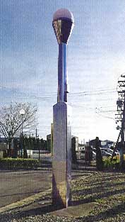
Each GPS receiver is housed in a 15-foot tall stainless-steel pillar. Readings are taken every 30 seconds. Using differential GPS corrections, horizontal motion of less than 0.1 inch can be detected. This level of accuracy may allow forecasting of earthquakes weeks or even months in advance. (Source: Discover, vol. 23 no. 3, March 2002)
Environmental Monitoring - Weather Forecasting
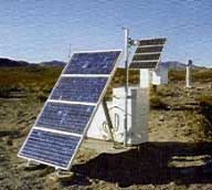
The National Weather Service releases weather balloons twice daily from more than 100 sites across the U.S. These balloons are now equipped with GPS technology to provide more accurate time and location at which temperature, humidity, pressure and wind speed and direction readings are taken. GPS equipped balloons are also being used for monitoring ozone holes over the polar regions.Environmental Monitoring - Wildlife Management
GPS technology is finding multiple uses in wildlife management. For example, threatened and endangered species have been fitted with tiny GPS receivers and radio transmitters to allow researchers to determine population distribution patterns, foraging range, and possible sources of diseases. GPS is also invaluable for wildlife research in areas where traditional surveying is impractical or impossible, such as in deep jungles and untamed areas such as the Amazon Basin.Commercial Applications - Fleet Management
Fleet management is one of the fastest growing commercial applications of GPS. Users include businesses with fleets of trucks or service vehicles. Combining GPS technology with radio transmitters on service vehicles allows central dispatchers to efficiently direct service personnel to their next call. Medical teams can use the real-time knowledge of location of ambulances and emergency response personnel to efficiently and rapidly deploy resources to accident sites.Freight and moving companies are using GPS to monitor the location and speed of their tractor-trailers traveling cross-country. Whereas the drivers may not like having the home office know exactly when and where they are stopped for meals, breaks or sleeping, or how fast they are driving, the corporate advantages include better resource management, improved customer service, and better fuel economy. In the near future, customers will likely be able to track the location of their shipments via the Internet.
With time, fleet management applications are becoming more sophisticated. For example, one system combines GPS capabilities with sensors to measure the amount of concrete in ready-mix concrete trucks. This allows the central office to monitor exactly how much concrete is available in which trucks, without having to rely on reports from the drivers. This capability facilitates real-time re-allocation of resources as needs change, reduces waste and errors, provides better service, and saves money.
Engineering - Monitoring the Dynamics of a Suspension Bridge
The 4,518-foot-long Tsing Ma Bridge in Hong Kong is the longest suspension bridge in the world and carries both road and rail traffic. The bridge is designed to sway and bend and can tolerate high typhoon winds that can send it swinging several feet from side to side. The passage of trains and heavy road traffic can also cause the main span to dip by more than two feet.
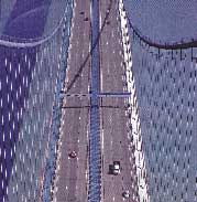
Because loads that exceed the design parameters and/or excessive motion could trigger catastrophic failure, a GPS array determines the exact position of the bridge in three dimensions ten times a second. Fourteen GPS receivers are attached to the cables, decks and towers of the bridge. The receivers relay their position to a computer at a central monitoring facility. The position of the bridge is then displayed in real time to within four tenths of an inch horizontally and less than eight tenths of an inch vertically. The computer also monitors wind speed and direction and estimates stress on the various components of the bridge. (Source: Discover, vol. 23 no. 3, March 2002)
Engineering and Construction - Equipment Control and Monitoring
In addition to the improvement in the speed and efficiency of precision surveying, a number of other GPS applications have been developed in engineering and construction. For example, GPS equipped earth moving equipment can now excavate and grade complex foundations with minimal operator interference. GPS technology not only guides the path of the equipment, but can also be used to automatically control the height of blades or scrapers. This capability results in significant cost savings and efficiencies, since periodic manual surveying is not required.The construction rental industry is also using GPS to monitor, in real-time, the location of equipment and details such as hours worked, engine revolutions, oil pressure and other critical parameters. This allows owners to ensure that their equipment is being used within specifications, helps manage maintenance scheduling and minimizes theft.
Agricultural Applications - Yield Mapping
Farm machines designed to harvest grain or wheat have been fitted with yield monitors that continuously track and record how many bushels are being harvested. At the same time, a GPS unit attached to the machine stores position information for later processing. After the harvest is complete, the yield monitor data is combined with the GPS data to generate a map of the farm showing distribution of yields. This information can be used for planning fertilizer distribution and irrigation. Multi-year information can be used to track health of the soil and production. Farmers using such systems have been able to significantly reduce fertilizer use, thus demonstrating the cost effectiveness and environmental benefits of the technology.Geosciences - Project EarthScope
The EarthScope project, with funding through the National Science Foundation, is designed to investigate the geologic structure of the North American Continent and study the processes leading to earthquakes and volcanic eruptions. By integrating GPS and telecommunications technology with geology, seismology, remote sensing and geodesy, scientists hope to extend our understanding of the ground beneath us.Scientists will install an array of 400 seismometers across the contiguous 48 states and Alaska, occupying 2,000 locations at intervals of 70 kilometers over a 10-year period. In the western U.S. and Alaska, GPS stations will measure how the North American crust is deforming, what motions occur along faults, how earthquakes start and how magma flows beneath active volcanoes. GPS and earthquake data will be integrated with detailed images from space and sensors placed in deep borings.
It is intended that data collected during the Earthscope project will be freely available online. This will allow scientists, researchers and even high school students to access and study how our continent is changing through time. (source: Geotimes, vol. 47 no. 2, April 2002)
Precision Navigation - Docking a Supertanker
Supertankers, the world's largest commercial seagoing vessels, can be more than 300 meters (975 feet) in length, and can carry as much as 300,000 tons of crude oil. Top speed fully loaded can be as high as 30 kilometer per hour (18 mph). The inertia of these ships is enormous. A crash stop maneuver (from "full ahead" to "full reverse") to stop a fully loaded supertanker requires about 3 kilometers (1.8 miles) and 14 minutes. The turning radius of these ships can be more than 2 kilometers (1.2 miles).
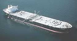
GPS is an integral part of supertanker navigation, and is critical for successful docking, since maneuvers and speed changes take so long to effect the ship's trajectory. GPS and navigation computers allow most supertankers to be driven by a single person, all while taking into account the effects of currents, tides and winds.
Miles from Nowhere- Measuring Subsidence of Offshore Oil Platforms
When offshore oil platforms extract oil from the subsurface, the seabed and the oil platform subside. The amount of subsidence is of great interest since it provides information about the extent and behavior of the oil reservoir. It is also a safety issue, since subsidence brings the rig closer to the sea surface and potentially damaging waves. Prior to GPS, it was very difficult to measure this subsidence, due to the lack of fixed reference points. GPS technology allows monitoring of multiple rigs from a local onshore base station. Regular interpretation allows analysis of the dynamics of subsidence as oil is extracted while also ensuring the safety of personnel and equipment.Military Applications - Operation Desert Storm
GPS played its first major military role in Operation Desert Storm. With GPS, U.S. forces were able to travel and maneuver at night and during sandstorms. Initially, more than 1,000 portable commercial receivers were deployed. By the end of the operation, over 9,000 units had been issued to troops, attached to vehicles, helicopters and aircraft instrument panels.

Military GPS units were used by F-15 fighters, aerial refuelers and B-2 bombers. Navy ships used GPS for rendezvous, minesweeping and aircraft support operations. GPS has become important for nearly all military operations and weapons systems, including fully autonomous operation of unmanned aerial vehicles used for surveillance. It is also used on satellites for positioning and to control spacecraft orientation.
Precise Timing Applications - High Voltage Energy Transmission
GPS technology can be used for applications requiring precise timing, independent of the location capabilities of the system. For example, a major power producer in the U.S. uses GPS timing capabilities for coordinating power distribution to multiple local utilities and bringing generating resources online and offline. Advanced applications include locating power line faults by timing exactly how long an injected signal takes to reflect back to the monitoring point from a break in the line. The advantages of GPS for such precise timing applications include accuracy, reliability, coverage area, portability, and cost-effectiveness, especially since the U.S. government takes care of maintaining the GPS system.Selecting a GPS Receiver
Potential GPS users are currently faced with a wide selection of GPS receivers from a number of commercial manufacturers and re-sellers. Before looking at receiver equipment, a number of issues should be considered depending on your intended use. Note that once you have GPS, you may well find additional uses for it. Therefore, you should consider buying equipment that has more features or higher accuracy than you think you need now, for you will likely discover uses for which you wished you had those features.The first issue is the internal design of the receiver. There are three basic designs: sequential, multiplexing, and parallel. Characteristics of each are presented in the following sections.
Sequential Receivers
Early GPS receivers were single channel, sequential receivers. This meant that they could only receive signals from one satellite at a time. They would then move to the next satellite and gather its data. The advantages were fewer components, lower power consumption and lower cost. In general, this type of receiver is sluggish and prone to higher noise and poorer accuracy than newer models.Sequential receivers also were manufactured with multiple channels. This means they could receive signals from multiple satellites at the same time (usually 2 or 3). This improved performance, but was more costly, used more power, and still required some sequencing to capture data from 4 or more satellites.
As component costs have come down, single and multi-channel sequential receivers have faded in popularity and are rarely manufactured. They are mentioned here because they are still available in the used equipment market.
Multiplexing Receivers
Multiplexing receivers usually contain one, two or three channels. But rather than sequencing from one satellite to the next, they "time slice" their data acquisition. This means they only gather partial data from one satellite before moving on to the next. They eventually get back to the first satellite and finish gathering the data. This is a trick used by manufacturers to have limited hardware appear to be tracking multiple satellites simultaneously. However, such equipment is actually no faster or more accurate than a sequential receiver with the equivalent number of channels. Multiplexing receivers are fine under ideal conditions with clear view of the sky. In marginal conditions, such as heavy tree cover or among tall buildings, problems arise when the receiver "loses" one satellite while jumping to others. Since the hardware is limited, these receivers don't track all visible satellites, but usually select the best four for computing a fix. Therefore, you don't get the accuracy advantage from having more than four satellites in view, and the system has to start over if one of the four selected satellites fades from view. This may lead to unexplained jumps in your calculated location, as different satellites come into view.Parallel Receivers
Parallel receivers all have multiple channels, usually between 5 and 12. Each channel is dedicated to a single satellite and synchronized to it. Such receivers are faster at calculating positions, since all satellite data is received in parallel. Positions tend to be more reliable, since the receiver is less prone to confusion if satellites temporarily disappear behind buildings or trees, or fade over the horizon.The minimum number of channels needed for a fast, 3-dimensional position is 4. However, that leaves no spares to track other satellites and improve accuracy, nor to lock onto new satellites that come into view as others drop over the horizon. Therefore, in practice, 5 channels is considered the minimum for a good receiver. However, having more than 5 channels allows for positioning even if satellites temporarily disappear behind buildings or trees. Parallel receivers are available with as many as 12 channels. This allows tracking 12 satellites at once. Having 12 satellites in view at once for any length of time is quite rare, however, so this may be a little overkill. However, a 12-channel receiver does provide redundancy and ensures that all visible satellites are considered in the solution.
As costs continue to come down, the difference between 5 and 12 channel parallel receivers will not be significant when the advantages of the 12-channel receiver are considered. A few commercial receivers advertise 24 channels. These units dedicate 12 channels to the U.S. GPS system and 12 channels to the Russian GLOSNASS system. Manufacturers claim higher positional accuracy when both systems are accessed simultaneously.
Single Frequency, Dual Frequency, Carrier-Aided and Carrier-Phase Receivers
In addition to the basic design of the receivers described above, there are variations in their method of operation. As explained earlier in this course, GPS satellites transmit data at two different frequencies, called L1 and L2. Data on the L2 frequency is encrypted and is reserved for military and other authorized users.
The simplest commercial receivers process the L1 frequency data to compute position. These are called single frequency receivers and, unless combined with DGPS, have a basic accuracy of about 10 meters (30 feet). At the next level up, single frequency receivers process the data on the L1 frequency and measure the exact starting time of data transmittal, thus providing increased positional accuracy. Such receivers are known as single frequency, carrier-aided tracking receivers.
The next level up are dual-frequency receivers. These receivers compare the L1 frequency with the L2 frequency to directly measure errors due to atmospheric effects. Such capability can improve positional accuracy by as much as 5 meters or more. These receivers achieve this accuracy improvement without decoding the encrypted data on the L2 frequency, and so are permissible for general civilian use. Carrier-aided tracking is usually included with dual frequency receivers to further improve accuracy, but it doesn't hurt to check the specifications.
At the highest end are carrier-phase receivers. These systems are capable of sub-centimeter accuracy, but require a differential GPS base station. Such systems also require continuous, uninterrupted view of the satellites during the survey, and so are best used for surveying tasks in large open areas.
The primary advantage of the higher-level receivers is accuracy of positioning. The major drawback is cost. Also, surveying with carrier-phase receivers requires considerable planning and careful execution.
Intended Uses of the GPS System: Navigation vs. Mapping vs. Surveying
There are fundamental differences in the features of GPS receivers designed for navigation versus those designed for mapping and surveying. For navigation purposes (on land or over water), the equipment should allow you to enter a course as a series of way-points, then the receivers display distance and heading to each way-point in turn, including estimated time to reach each way-point. Systems that display base maps (like street maps, topographic maps, aerial photos or marine navigation charts) on a screen and include your location are considered navigation systems. These systems take frequent readings (for example one reading per second) and continuously display position, heading, and speed. Some provide a "backtrack" function, which stores your location data so you can return the way you came.Mapping and surveying systems are designed for high accuracy, point data collection and are optimized for collecting data to be later exported to an external database or mapping software. These systems expect that you will stop at a location to be surveyed and take a number of readings at rest. They usually do not include base map displays, as they are specifically designed to determine the location of known points. For example, municipalities use such units for mapping manhole covers or other utilities. They are also used in the geosciences, for example, to get coordinates of installed monitoring wells or measurement points along geophysical surveys. A number of applications also exist in engineering, landscape architecture, surveying, oil and gas work, and other disciplines where high-accuracy is required. These systems typically require differential GPS base stations to maximize accuracy. Sophisticated software packages are available for post-processing and integrating with Geographic Information Systems (GIS) and/or Computer Aided Design (CAD) programs.
Mapping systems are typically configured as a backpack system, with the electronics and power supply in the backpack, and the antenna either fixed to the backpack or mounted on a hand-held staff. Surveying systems typically use a tripod-mounted antenna for stability. The backpack systems provide for more rapid data collection at the expense of some accuracy.
Area of Use: Marine vs. Land vs. Aviation
A number of GPS units are designed strictly for marine use, and are specified as such. These units do not allow the selection of different map datums. Datum capability is critical for land navigation, positioning and surveying tasks, since topography on land is variable. Equipment made for marine use is not concerned with topographic complications, since the surface of the ocean can be approximated by a simple mathematical model. Marine equipment is primarily designed for navigation, ease of plotting routes and staying on course. Options on marine equipment include fish finders and sonar for determining and displaying depth of the water. Some include other features such as estimated fuel usage. Such features require additional specialized transducers.Aviation uses require a special breed of GPS receivers for use in assisted landings or for precise navigation. For such applications, it is considered unwise to buy less expensive equipment not designed for aviation use.
Portable, Transportable and Fixed Installation
Portable GPS receivers come in a variety of sizes, including as small as cell phones or as add-on cards for personal digital assistants (PDA's), laptop computers, or pocket-style personal computers. At the next level are transportable units which come typically as backpack style, where all the electronics and batteries are carried on your back. You usually have the option of installing the antenna on the backpack or mounting it on a hand-held staff. The highest accuracy transportable systems are tripod-mounted, and are used primarily for very high-accuracy surveying tasks.Fixed installation units are designed for permanent or semi-permanent installation on boats, vehicles, construction or agricultural machinery, robots, etc. These units typically come as separate components, with the antenna separate from the electronics and display. These units also typically require an external power source. Antennas are usually in rugged weatherproof enclosures. The cost and complexity vary by application, from the least expensive marine navigation units to the most expensive precision machine control systems.
Stand-alone vs. Integrated units
Early GPS receivers were strictly stand-alone. All the needed features were built into the receiver. There are still many stand-alone systems. Recently, there have been advancements in making GPS as add-ons to Personal Computers (such as laptops), pocket-type PC's, PDA's (personal digital assistants), and even in combination with cell phones. Integrating GPS with existing computer and display equipment allows multiple uses for the PC including GPS, as opposed to buying dedicated GPS equipment. Topographic maps, NOAA marine charts, aerial photographs of harbors or land areas are available to make the PC/PDA a complete navigation system.Additional Factors to Consider
Once the designs, method of operation, and intended use issues have been addressed, there are additional factors to consider. Such factors are briefly described below.Accuracy Warning and System Status - Most receivers have some sort of indicator that flags when accuracy may be reduced due to reduction in number of satellites in view, poor reception or other errors. Receivers should also display the number of satellites in view, and indicate when they are occupied downloading empheris or other information from the satellites rather than calculating position.
Differential GPS Capabilities - There are many options for improving accuracy using differential GPS. Many receivers are able to receive the free Beacon and WAAS correction signals as a standard feature. Some also are equipped to receive a number of the subscription correction services, as either a standard or optional feature. Higher-end units are DGPS ready for use with any number of correction services, including setting up your own local base station.
Battery Life - Battery life must be considered if you plan on using GPS in remote areas for extended periods. Some units allow "hot swap" of batteries without losing data stored in the unit (this feature may also be termed 'internal backup battery'). Some allow external power supplies such as cigarette lighter adapters for your car, or larger external battery packs. Fixed units usually require external power sources.
Screen Display - For units with screen displays, the number of pixels and size of the screen will determine how much information can be displayed and how detailed or viewable the data. Inexpensive hand-held units trade size for screen display area and are generally monochromatic or grayscale. Color displays on portable units are more attractive, but require more power. Automotive display units opt for larger screens and color capabilities since the vehicle provides power. Marine units come in a wide variety of display options, depending on your budget and needs.
Size and Weight - Screen size and power source will usually dictate the size and weight of the receiver. If the unit is to be hand-held or carried in a backpack for long periods of time, the total weight should be a consideration.
Antenna Configuration - On small portable units, the antenna is integral to the case. Larger units or add-ons to computer equipment may have one of two types of antennas: quadrifilar or patch. Quadrifilar antennas are a length of coiled wire in a plastic housing. For automotive use, removable quadrifilar antennas are an advantage in that they can be placed forward on the dashboard for better satellite view. Quadrifilar antennas are best at receiving signals from satellites lower in the sky. Patch antennas are flat, and are usually built into the receiver. These are better at detecting satellites directly overhead.
Units designed for fixed mounting usually have separate antennas. Protection of the antenna must be considered in context of the intended use. For example, marine navigation antennas are usually mounted in rugged, weatherproof enclosures. High accuracy mapping and survey work requires external antennas mounted on staffs or tripods. If multipath errors are a potential problem, special antennas are available.
Internal Maps - whereas all GPS receivers calculate position, many display base maps. The level of detail of built-in maps varies considerably. Options may include downloading maps from computers, CD-ROM or purchasing detailed map cartridges.
Waypoint Capabilities - If the GPS system is to be used for navigation or route mapping, the ability to enter or store intermediate locations (waypoints) is important. Considerations include the number of waypoints that may be stored and the ability to annotate the waypoints so they can be used to map landmarks, markers or points of interest.
Track Logging - Track logging units allows recording your route as you travel. This feature allows backtracking and documenting the exact route taken. An important consideration is the amount of memory available for storage of route points. Another important consideration is the ability to "hot swap" batteries without losing all the information already in the unit.
Upload/Download Capabilities - Many units have a data port that allows connection to external computers or personal digital assistants. A data port allows downloading route and waypoint information from the GPS unit to the computer/PDA for storage and later use, making maps, etc. This capability provides virtually unlimited offline storage and allows re-use of the GPS internal memory. Data ports should work both ways, so that you can upload information from your computer into the GPS unit. Newer units may provide wireless transmission capabilities to appropriately equipped computers.
Sunrise/Sunset Times - Some receivers can calculate sunrise and sunset times based on your location. This may be helpful in planning and scheduling.
Odometer and Speedometer -The odometer function reports how far you have traveled since last reset. The speedometer function displays current speed. Note that many receivers have a maximum speed they can display. Many consider this a "feature" designed to prevent pilots and automotive users from using the less expensive units.
Measurement Units - Most receivers will allow selection of display units, such as miles, nautical miles, kilometers, etc. The ability to mix units may be useful, for example, if you want elevation in feet but distance in miles.
Pre-Loaded Database - GPS receivers designed for aviation or marine use may have landmarks such as ports, airports, etc. pre-programmed into the unit.
Ruggedness/Waterproofing - Depending on intended use and abuse, you should consider how rugged and waterproof the system is. Some receivers claim only weather resistance while others are completely waterproof.
Mounting Options - Depending on your intended use, options such as tripod-mounts, dashboard mounts, handlebar mounts, etc. may be useful.
Other Features - Other features available on various units include voice guidance (automotive), electronic compass, and barometric altimeters.
Warranty, Service and Return Policy - As with any electronic device, issues of warranties and service should be considered. Some manufacturers only sell direct (especially high-end equipment), while others sell through re-sellers in retail locations an/or on the Internet. Return policies and service are important considerations.
Conclusion
The Global Positioning System and the availability of free and fee-based correction signals has revolutionized navigation, mapping and surveying. With the advent of low cost receivers, GPS is being used by thousands of people for applications ranging from recreation to wildlife research to fleet management. Knowing how GPS works, its limitations, and the techniques available to improve accuracy should allow you decide what equipment you need and how it should be used. The key to selecting the right equipment is the ability to define your present and potential future needs, understanding the technical specifications published by the manufacturers and knowing what questions to ask.Glossary of Terms and Acronyms used in this Course
A/S - see Anti-Spoofingalmanac - the GPS term for the parameters that approximately describe the orbits and locations of all GPS satellites at a given time.
anti-spoofing (A/S) - reference to the encrypting of the precise positioning information (the P-Code) in the GPS signal to prevent unauthorized use.
augmentation - the GPS term for increasing accuracy of GPS locations by incorporating differential GPS correction factors.
Beacon - reference to the GPS augmentation system operated by the U.S. Coast Guard, consisting of 76 base stations primarily around popular harbors and waterways. Differential correction data is transmitted via radio signals.
C/A - see Coarse Acquisition Code (referred to by some literature as the Civilian Access Code)
carrier - the transmitted GPS radio signal that has information embedded in it.
coarse acquisition code (C/A) - that part of the GPS data stream that uniquely identifies the satellite and provides the basis for travel time determination by the receiver.
constellation - In GPS terminology, refers to the number and distribution of satellites currently in orbit.
Control Segment - that part of the GPS system than includes ground tracking stations and the Master Control Station operated by the U.S. government.
DGPS - see Differential GPS
Differential GPS (DGPS) - the use of at least one fixed GPS receiver at a known location in order to calculate the error in GPS position.
Dilution of Precision (DOP) - the effect of satellite geometry on the accuracy of the calculated position.
DOD - Department of Defense
DOP - see Dilution of Precision
Dual Frequency Correction - the use of both the L1 and L2 GPS carrier frequencies to directly measure the effect of the ionosphere on pseudo-range calculations.
ephemeris - the GPS term for the parameters exactly describing the position of a given satellite (within about 1 meter (3 feet)).
geodesy/geodetic - referring to study of the shape of the earth (geodesy) and the surveying of points on its surface (geodetic).
geo-stationary satellites - see geo-synchronous satellites
geo-synchronous satellites - communications satellites in orbits that keep the satellite fixed relative to a point on earth.
GLOSNASS - the Russian Federation's equivalent of GPS
GPS - Global Positioning System
Inverse DGPS - a system by which data from a number of roving receivers is transmitted to a central location before a differential correction is applied. Used primarily in fleet management applications.
ionosphere - that portion of the earth's atmosphere extending from about 80 kilometers (50 miles ) above the earth's surface to about 1,000 km (600 miles) into space.
L1/L2 - GPS radio signals are broadcast at two frequencies, termed L1 and L2.
LAAS - see local area augmentation system
local area augmentation system (LAAS) - a differential GPS system operated by the Federal Aviation Administration around airports. Correction factors are transmitted to specially equipped aircraft receivers via very-high frequency (VHF) radio signals.
multipath error - the receiving of multiple signals from the same satellite due to reflection off buildings, water bodies, rock faces or other reflective surfaces. Also known as multipath distortion.
Navigation Message - part of the GPS data stream, which includes satellite location information and other system data
Navigation Satellite Timing and Ranging (NAVSTAR) - the official name of the GPS system
NAVSTAR - see Navigation Satellite Timing and Ranging
P-Code - see Precision Code
Post-processing DGPS - the technique of storing GPS readings from roving receivers and a fixed reference station until the end of the survey, then calculating and applying corrections. see also Real-time DGPS.
PPS - see Precise Positioning Service
pseudo-range - the name given to the initial calculated distance from a satellite to a GPS receiver
Precise Positioning Service (PPS) - the information transmitted by the GPS satellites that provides the U.S. military and other authorized users high-accuracy location data. This consists of the Navigation Message and the encrypted P-Code.
precision code (P-code) - part of the GPS data stream that lets military and other authorized users determine more precise locations. This information is encrypted.
PSAP - see public safety answering point
public safety answering point (PSAP) - location of 911 operators
Real-time DGPS - the technique of calculating GPS error terms in real time at a fixed base station and transmitting correction factors to roving receivers via radio or satellite link. see also Post-processing DGPS.
S/A - see Selective Availability
Selective Availability (S/A) - intentional degradation of GPS timing and/or satellite position data to decrease the accuracy of calculated position.
solar radiation pressure - the force exerted on an object due to being hit by photons of light from the sun or sunlight reflected from other heavenly bodies.
segments - In GPS terminology, the divisions of the GPS system. There are three segments: the Space Segment, the Control Segment and the User Segment
service volume - the space in which GPS positioning is designed to work. It extends from the earth's surface to approximately 5,000 km (3,000 miles into space.
Space Segment - that part of the GPS system than includes all the satellites, also known as space vehicles or simply SV's
space vehicle (SV) - official name of the GPS satellites
SPS - see Standard Positioning Service
Standard Positioning Service (SPS) - the information transmitted by the GPS satellites accessible to any user for use in determining location. This consists of the Navigation Message and the Coarse Acquisition code.
SV - see space vehicle
troposphere - in GPS usage, the portion of the atmosphere composed of the troposphere, the stratosphere and mesosphere, extending from the earth's surface to about 80 kilometers (50 miles) up.
User Segment - that part of the GPS system that includes all military and civilian users
WAAS - see wide-area augmentation system
wide-area augmentation system (WAAS) - a network of about 25 ground reference stations operated by the Federal Aviation Administration for providing free differential correction data via geo-stationary satellite.
(end)