Acknowledgments
The instrumental contribution of Genny E.
Pond, a former graduate research assistant, Department of Civil and
Environmental Engineering, Clarkson University, Potsdam, NY, to the development
of the first version of the software is appreciated.
The contributions of Camille
Rubeiz, PE, and Douglas Raby of AISI, Michael A Grubb, PE of BSDI, Ltd.,
Professor Karl H. Frank, PE of the University of Texas at Austin, Edward P.
Wasserman, PE, and Henry Pate of the Tennessee Department of Transportation,
Ralph Anderson, PE, and Richard Best, Tim Armbrecht, and Paul Johnson of the
Illinois Department of Transportation, William Rogers, PE, Robert Woodruff,
Christian Ray, and Tom Koch of the North Carolina Department of Transportation,
Bob Lyon of HNTB, Roger Eaton, PE, and Patti Ritchey of HDR Engineering, Inc.,
Pittsburgh, PA are gratefully acknowledged.
The development of the
software was funded by the AISI Transportation and Infrastructure Committee.
Notice
This manual is to be used as
guidance while using AISIsplice software.
In no case shall it be used as a substitute for competent professional
assistance. The user assumes all
liabilities and does so at his/her own risk.
ã 2001
American Iron and Steel Institute
All
Rights Reserved
Table of Contents
Forward. 4
1. Scope of Software. 5
2. Software Installation. 5
3. License Activation Procedure. 6
4. Starting the Program.. 8
5. Software Input 8
5a. Welcome
Screen. 14
5b. Loading Input Screen. 15
5c. Girder
Properties Input Screen. 16
5d. Additional
Properties Input Screen. 17
5e. Splice
Properties Input Screen. 18
6. Saving Input Data. 18
7. Execution of the Software. 19
8. Software Output 20
8a. Splice Design
Summary Graphics. 20
8b. Splice
Analysis Summary Graphics. 21
8c. Report Output 22
9. Exiting the Software. 23
10. Review of Computer Output 23
11. Suggestions for Maximum Economy and
Performance. 24
Appendix A -
Default Values. 25
Appendix B - Report
Outlines. 33
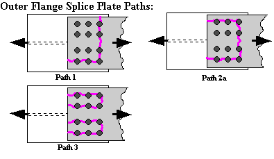
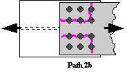
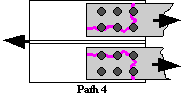
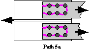
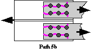
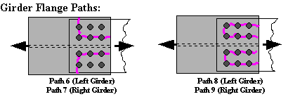
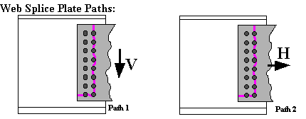
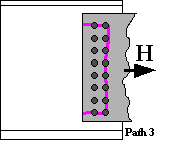
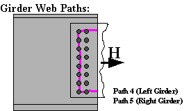
Appendix C - Block
Shear Rupture Paths. 34
Appendix D -
Software Limitations. 35
Appendix E -
References. 36
Appendix F - Sample
of Bridge Splices Designed By AISIsplice. 37
In
1999, the American Association of State Highway and Transportation Officials
(AASHTO) adopted a new methodology for the design of bolted field splices of
flexural steel members. The new
methodology was developed in response to the lack of a uniform design
methodology for bolted splices, which resulted in confusion and costly splices.
The
new methodology was based on the analytical and experimental research program
conducted by Firas I. Sheikh-Ibrahim and Karl Frank (1996, 1998, 2001) at the
University of Texas at Austin. In the
new methodology, two approaches for splice designs were justified. In the first one, the web is designed to
resist its share of the moment, and the flange splices to resist the moment not
resisted by the web. In the second approach,
the flange splices are designed to resist the total design moment, and the web
splice to resist only the eccentric shear, which is applied at the centerline
of the splice.
Even
though the two aforementioned approaches were found acceptable from a resistance
standpoint, Sheikh-Ibrahim and Frank recommended that the second approach be
followed to yield the most cost-effective splices.
In
a step towards obtaining cost-effective splices, AASHTO adopted the first
approach as the primary design method, since a similar approach has been used
in bridge design practice, and has been incorporated in AASHTO for quite a long
time. Therefore, AASHTO developed their
99 Interim such as to illustrate the first design methodology in sufficient
details, and briefly touch on the second approach as an alternate method.
Since
significant changes have been incorporated in AASHTO, the AISIsplice software
was developed to help designers understand the new design methodology, and
produce cost-effective splices. The
software, in its current version, is limited to the first design approach
mentioned above, but it is anticipated that it will incorporate the second
design approach in the near future.
....................................................................................................................... Firas
I. Sheikh-Ibrahim, PhD, PE
AISIsplice
is a tool for the analysis and design of bolted field splices for straight,
right, I-shaped, steel girders. The
analysis and design process is based on the AASHTO LRFD Bridge Design
Specifications, Second Edition, 1998, including the 1999 interim.
In
the design mode, the software sizes and optimizes the splice plates and
bolts. In the analysis mode, the
software determines the adequacy of given splice plates and bolts. For both modes, performance ratios
(load/resistance) for all splice components are determined.
AISIsplice
runs under Microsoftâ Windows95/NTâ, or higher, on IBM
compatible personal computers. A free
hard-disk space of 8 MB is recommended,
along with a minimum of 8 MB memory (16 MB preferred). EGA, VGA or a high-resolution, color
graphics board and mouse are required. Small fonts should be selected for the
computer’s display font size setting.
AISIsplice
should be installed and run from the hard drive for efficient operation. To install AISIsplice on the hard drive:
1. Insert
CD in the CD ROM drive. (It is assumed
that the D: drive will be used. If
another drive is used instead, substitute the appropriate letter in Step 3.)
2. Click
Start on the Windows taskbar and
choose Run...
3. Type
D:SETUP in the text box and click OK.
4. Follow
the instructions in each succeeding window until the installation is completed,
then click Finish.
AISIsplice will automatically appear in the Programs menu and can be used to access
the software as described subsequently.
To access the software easily, you may wish to create a Shortcut AISIsplice Icon and drag it to
the desktop.
AISIsplice has a 30-day, ready-to-try license. You can install it on any computer, and you
are entitled to distribute it to anyone without permission. The software will run for 30 days from the
day of installation, and will need re-activation after expiration of the trial
license.
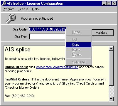
After the expiration of the free trial period, the
License Configuration screen will appear when you attempt to run the software.
If you want to copy the Site Code number to the clipboard, highlight the Site
Code and click the right mouse button. When the menu shown below appears,
select the Copy option. You will need to use this number when you
request your activation code.
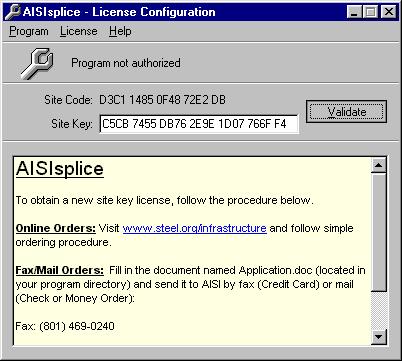
After you have your Site Code ready, follow one of
the two procedures explained herein to obtain a new site key license. For online orders, visit www.steel.org/infrastructure
and follow simple ordering procedure.
For fax or mail orders, fill in the document named Application.doc
(located in your program directory) and fax it to AISI at 801-469-0240 (Credit
Card), or mail it to (Check or Money Order):
Transportation and Infrastructure Group
American Iron and Steel Institute
1101 17th Street NW Suite 1300
Washington, DC 20036
When you receive your activation code type it, or paste
it into the Site Key box shown below and then click the Validate button.
The software will then check your Site Code and the
message shown below will appear to prompt you that you are licensed to run the
software.
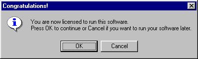
After you click the OK button, the License Flash
screen shown below will appear. This screen will also appear every time you run
the software. Note that this screen
informs you of the duration of your remaining license. While the License Flash screen is visible,
you can activate the License Configuration screen by hitting the Enter
button on your keyboard.

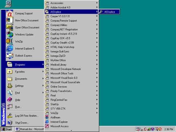
To
start AISIsplice, click Start on the
Windows taskbar, point to Programs folder,
then AISIsplice folder (it is
assumed herein that the default folder was not altered during the installation
of the software), and then click AISIsplice. The software will open the Welcome Screen.
If
a shortcut was created on the desktop, double-click the shortcut icon, and the
software will open the Welcome Screen.
When
AISIsplice is opened, the Welcome screen will appear. AISIsplice was designed using a “Wizard” approach. Input Screens are sequentially ordered, and
the user is allowed to move forward and backward from each screen by clicking
the Next and Back buttons, respectively.
When the information is completely entered for a given screen, the user
should click the Next button. The user will either be allowed to progress
to the next screen, or will be directed to enter incomplete, or fix inaccurate
input values. The Back button may be clicked at any time, to revise previously
entered values.
The
wizard approach was used to minimize the use of menu systems. However, a minimal menu system is provided
including the following:
File menu:
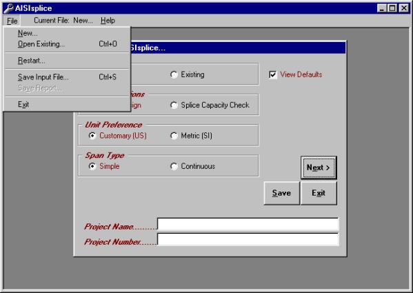
The File menu
includes the following options:
New - allows the user to create
a new input file.
Open Existing - allows the user to open and revise a
previously saved input file.
Restart - allows the user
to return to the Welcome Screen at any time.
Save Input File - allows saving the current input file.
Save Report -
allows saving the output report created during program execution (only
available from output screens).
Exit - allows the
user to quit the program.
Current File bar:
This Current File bar informs the user of the path/filename of
the current input file.
Help menu:
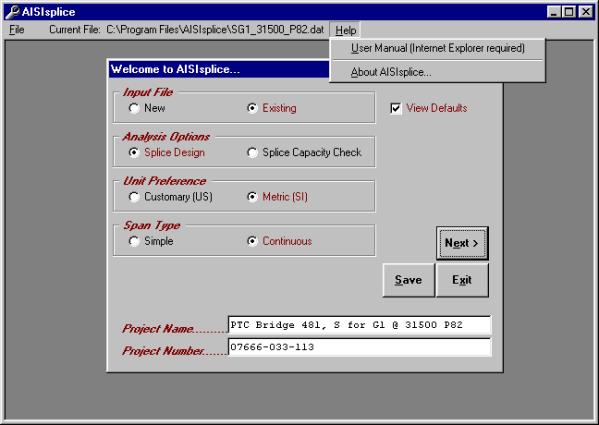
Two
options are available from within the Help menu; User Manual and About
AISIsplice options.
User Manual:
The
User Manual menu option enables you to view the User Manual from within
AISIsplice. At this time, the online
User Manual can be viewed using Internet Explorer only. If you have problem with your Internet
browser or have a different browser, you can view the User Manual using Word.
The User Manual is named Manual.doc and is placed in your program directory,
and on the distribution CDROM.
About AISIsplice:
The
About AISIsplice screen contains information about AISIsplice, along with
hyperlinks to AASHTO, RCSC, and AISI web pages.

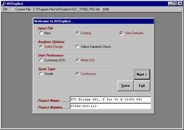
The
Welcome screen prompts the user to create, open, and revise an input file. This is the starting point for any design or
analysis. It has the following options:
·
New - click
to create a new input file.
·
Existing - click
to revise an existing input file. If you already have an existing input file
open and wish to open a different one, double-click on this option.
·
Splice Design
- click to have the software design a splice for the given
loading and girder properties.
·
Splice Capacity
Check - click to have the software check the adequacy of a given splice for
given loading and girder properties.
·
Customary (US) or Metric (SI) - click to select the
units system of choice.
·
Simple or Continuous - click to indicate the type of bridge span under consideration.
·
Project Name
- (optional) allows the user to type a project name in the box provided
(limited to 40 characters in length).
·
Project Number
- (optional) allows the user to type a project number in the box provided (also
limited to 40 characters in length).
·
View Defaults
- when checked, allows the user to view and alter file default values (refer to
Appendix A for more information on AISIsplice default values screens).
To
develop a new input file, click the New
option and select the appropriate Welcome screen options. If you wish to create user-specific
defaults, click to place a check mark in the View Defaults box (refer to Appendix A). When finished, click the Next
button to proceed to the next screen.
To
open or revise an existing file, click the Existing
option. In order to provide software
guidance, an input file is distributed with the AISIsplice software. The file, which is called “SG1_31500_P82.dat”,
will be used in this manual as an example of a software-generated splice
design. The example is for a splice located near the dead-load contra-flexure
point. The loadings in the example are
those of a splice that was designed by HDR Engineering-Pittsburgh for a
two-span continuous, 20 degree-skewed, Slab-on-I-girders composite bridge on
the Pennsylvania Turnpike in Somerset County, Pennsylvania. To open SG1_31500_P82.dat, click the Existing option. When asked to save the current file, click No.
When the Open dialog box
appears, click the file named SG1_31500_P82.dat (making sure the appropriate
directory is accessed) and then click Open. After SG1_31500_P82.dat is opened, the
Welcome screen will look like the one shown above. When you are ready, click Next
to continue.
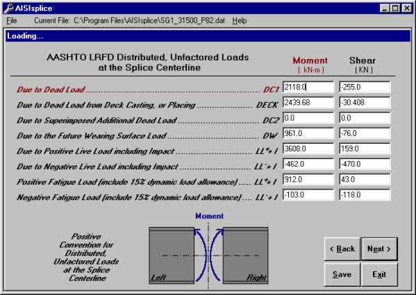
The
Loading screen enables the user to enter the unfactored moments and shears that
are applied at the centerline of the splice.
The positive convention is denoted on the elevation graphic. Negative moments are not accepted for
simple-span bridges.
If the SI units system is chosen, moments and shears
should be given in kN-m and kN, respectively.
These values should be given in k-ft and kips if the US units system is
chosen. When finished, click the Next button.
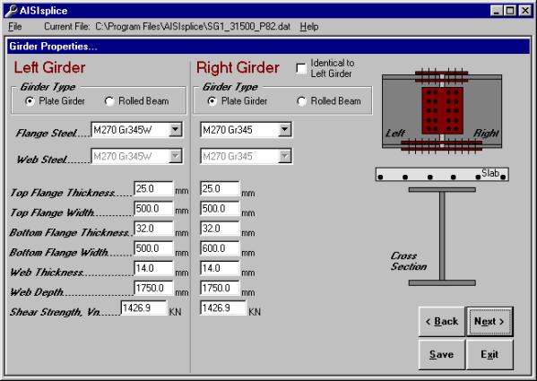
The
Girder Properties screen allows the user to enter the dimensions, material
properties, and shear strengths of the two adjoined girders. Select either Rolled Beams or Plate
Girders. Click to place or remove
the check mark in the Identical to Left
Girder box (right girder properties are filled automatically if
checked). Refer to the cross section
graphic for clarification on selected items.
Enter each girder’s nominal shear resistance as per AASHTO 6.10.7. Click
Next to continue.
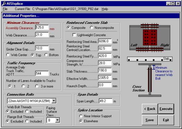
The
Additional Properties screen enables the user to specify minimum clearances
(for design) or number of splice plates (for analysis), alignment details,
traffic frequency, and connection bolt properties. The user also describes the
reinforced concrete slab, if composite design is chosen. The user also specifies the span length,
and, when applicable, the splice location.
For additional information, refer to the graphics and/or tool tips.
Click
Composite Design to utilize the
slab’s strength or Noncomposite Design to ignore it. For composite designs with lightweight
concrete, click to place a check mark in the LWC box. Enter zero for the
value of Reinforcing Steel Area when
the concrete slab’s reinforcing steel is not utilized. However, when the bars are utilized in the
resistance calculations, enter a combined area and respective centroid for an
equivalent single row of steel bars.
When
finished entering the data, click the Execute
button to perform the design or analysis process.
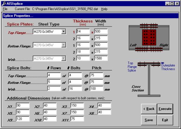
The
Splice Properties screen appears only during splice analysis. This screen includes the material properties
and sizes of the top and bottom flange and web splice plates. The screen also includes the number,
spacing, and pattern of connection bolts.
For
clarification on selected items, refer to the cross section graphic. When finished entering data, click the Execute button to perform the analysis.
Since
the Splice Properties screen is specific to analysis progressions, it will not
appear in the progression of Example SG1_31500_P82.dat, which is included in
this manual and the installation files.
However, after the software design process is completed, the generated
design can be modified and then re-evaluated by accessing the splice properties
screen via the Adjust Design button
(as discussed in section 7a).
Before
execution of the software, it is recommended that the input file be saved. If a new input file has not been saved
before the Execute button is
clicked, the user will be prompted to save it.
The user will also be prompted to save the current input file before
opening an existing file, creating a new file, or exiting the program.
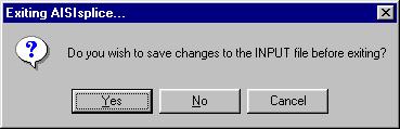
When prompted, click Yes to save the file as shown, No
to proceed without saving, and Cancel
to ignore the previous action.
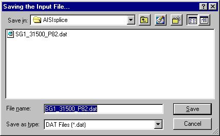
In
order to save an input file, one of two methods may be used. The Save button may be clicked on any
screen or Save Input File selected
from the file menu.
In
either case, the Save As dialog box,
which is shown to the right, appears.
The user may enter a new filename or update an existing file. Select the appropriate directory, folder,
file type and filename and then click the Save
As dialog box’s Save button.
After
entering the required input values, and after progressing through the
applicable screen sequence, execution of the software may be initiated by
clicking the Execute button found at
the bottom right of the screen (in the usual location of the Next button). Upon completion of the analysis or design, the output graphic
screen appears (shown in section 7a).
If
either girder is determined inadequate to sustain the given construction,
fatigue, strength, or service loads, the program will terminate. A warning, including information as to the
nature of the inadequacy, will be given.
If the user feels this warning message was reached in error, the
generated output report, written to the point of termination, can be viewed and
may contain additional, helpful information.
The software output consists of scaled graphics and a
detailed report. Graphic illustrations
include the elevation and cross section views of the splice and adjoined
girders. Graphical output includes
splice dimensions, bolt details, a summary of required filler plates, and
splice component performance ratios.
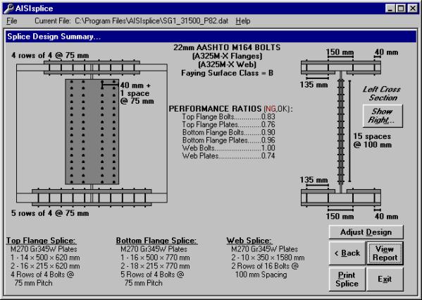
When
designing a splice, the Splice Design Summary screen appears. This screen contains graphical output of
splice details, required filler plates and their locations, girder cross
sections and elevation views, properties of the flange and web connection
bolts, faying surface class, and performance ratios.
If the
two adjoined girders are different in size, the left girder cross section will
be visible by default. However, by
clicking the Show Right button on
the right of the screen, the right girder will be displayed.
Generated
performance ratios for each splice component are based on the ratio of factored
load to the available factored resistance. A performance ratio exceeding unity
indicates a violation of the 1999 AASHTO-LRFD Specifications, and thus, compels
the user to adjust the splice properties, accordingly (i.e. thicken splice
plates, add more bolts, etc.). Due to
the improbability of block shear rupture modes controlling the design, their
performance ratios are shown on this screen only when their values exceed
unity.
The
user may print the graphics and given properties by clicking the Print Splice button at the bottom of
the screen. The report text (shown in
7c) may be viewed by clicking the View
Report button.
A
useful feature of AISIsplice is the Adjust
Design button. After a splice
design is generated by the software, the user may modify the design to his/her
preference. When this button is
clicked, all properties of the designed splice are loaded into the Splice
Analysis screen (as shown in section 4e), and the mode is changed from design
to capacity check. The user is sent to
the Splice Analysis screen to change selected properties of the splice. When the user selects the Execute button at the bottom of the
Splice Analysis screen, the splice will be analyzed and the Splice Analysis
Summary screen will appear (shown in section 7b).
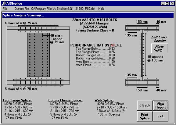
The
Splice Analysis Summary screen includes all components of the Splice Design
Summary screen, with the exception of the Adjust
Design button (since an analysis is performed instead of design, thus the Back button may be used). The software also informs the user of any
given spacing which does not satisfy the provisions of AASHTO 6.13.2.6.
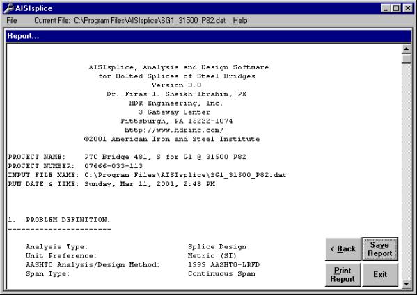
The
report generated during the software execution can be viewed by clicking the View Report button on the graphical
output screen. Once the Report screen is displayed, the user may use the
scrollbar on the right of the Report screen, to easily view and navigate
through the report.
To save the report, click the Save Report button on the screen, or
select Save Report from the file
menu. Then, follow the procedure given
in section 5. When naming an output
file, do NOT use the same extension
of the input files, to avoid overwriting the input file. The report may be opened with any
text-editing program.
By
clicking the Print Report button,
the report will be printed by sending it to the default printer. Likewise, the report may also be printed
using any text-editing program.
The
format of the report will vary slightly depending on whether a capacity check
or design is performed (refer to Appendix B for report outlines).
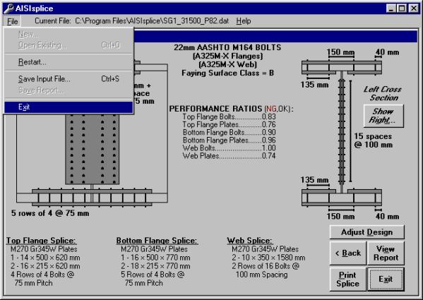
There
are several methods to exit the software.
From any screen, the user may click the Exit button at the bottom of the screen, or select Exit from the file menu. The user may also click the close button in
the upper right corner of the program’s window. The user will be prompted to save the current input file before
the program closes.
To
avoid having problems, losing data, or corrupting input files, always exit the
software by one of these three methods.
Since
the user assumes all liabilities, he/she user should review the computer output
carefully and thoroughly, to verify the analysis and design performed by the
software.
The
first section of the report lists all given input values and should be reviewed
by the user in order to verify the accuracy of the entered input used by the
software. If the problem definition
contains erroneous input values, then succeeding calculations and conclusions
are invalid.
At
each limit state, the flange design forces are calculated and written to the
report. These values should be reviewed
by the user to insure that the flange resistance is not exceeded. Although flange stresses are checked by the
software, it is important for the designer to know the efficiency of each
component. Also the user should review
the report section titled “3. SUMMARY
OF AASHTO DESIGN FORCES”. This section
gives all limit state design forces, which are used to determine the required
strength of a splice.
Several steps may be taken to reduce the cost of a
splice:
·
When
using AISIsplice in the design mode, utilize the Adjust Design button feature.
Modify splice properties to meet the needs of the project and the
inventory of the fabricator.
·
When
using AISIsplice in the analysis mode, try to optimize performance ratios by
selectively changing splice properties.
Keep the difference between inner and outer plate areas within the
specified percentage, (refer to Appendix A) in order to equally distribute the
force between the splice plates and, thus, decrease the number of required
bolts. Compare your design with the
AISIsplice automated design, and select the least-cost splice.
·
It
is recommended to use the faying surface class which will be present on the
girders’ surfaces. Using a faying
surface with a smaller surface condition factor (AASHTO 6.13.2.8) than what is
actually present may cause overly conservative splice designs. Blast cleaned surfaces, or surfaces with
Class B coatings, should be designed and analyzed using a class B faying
surface to obtain cost-effective splices.
·
Whenever
possible, opt to have the bolt threads excluded from the shear planes in the
flange and web splices.
·
When
bearing controls the design of the web bolts, increase the edge distance
slightly to increase the bearing resistance, and thus avoid using additional
web bolts.
·
Since
bolted splices are expensive to fabricate, make the use of all field splices
optional, to give the fabricator the option of selecting a least-cost
alternative.
The
Default Values screen allows the user to view all, and alter some of the AASHTO
load factors, resistance factors, bolt and splice details, load modifiers, and
minimum design loads. This is an optional portion of any analysis or design
progression, and will not be shown unless the View Defaults box is checked on the Welcome Screen. Click
the appropriate tab in order to change any of the default values used for
current input file calculations.
The
Reset Defaults button in the Default
Values screen allows the user to set all default values to their initial
software preset values, after having been altered.
The
Example “SG1_31500_P82.dat” input file uses altered default values, and will be
shown in this section. The load factors
used in the example are those of 1996 PennDOT’s DM4 for the P82 permit vehicle. This shows that the software can be used to
utilize state specific load factors.
Load Factors Tab:
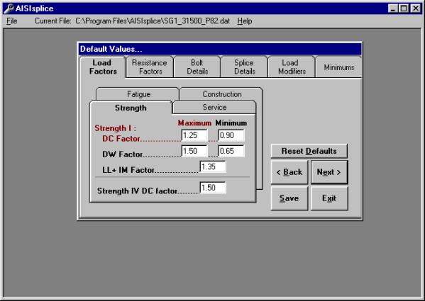
Access this tab to alter load factors for the construction, fatigue,
service, and strength limit states.
System defaults are taken from AASHTO 3.4.1 and 3.4.2. Maximum load factors must be greater than
minimum load factors and less than 3.0 (selected arbitrarily), while minimum
load factors may not be less than zero.
In order to conservatively neglect wearing surface loads which oppose
the live load moment, the user may elect to use a minimum wearing surface
factor, DW, equal to zero.
Resistance Factors Tab:
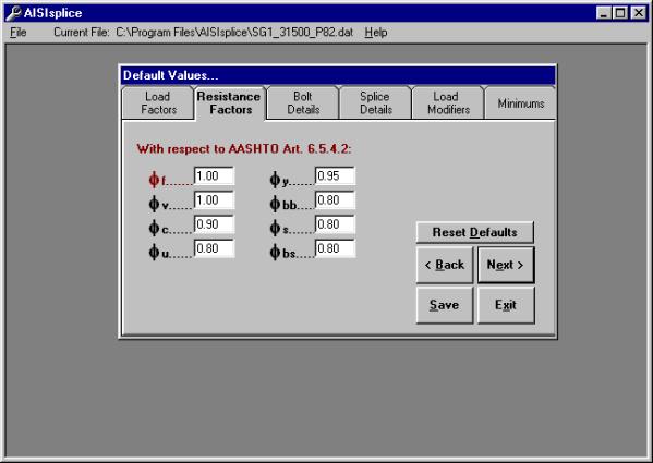
Click
this tab in order to modify resistance factors (such as those for tensile gross
section yielding, plate bearing, block shear, etc.) given by AASHTO
6.5.4.2. Resistance factors which are
less than 0.50 or greater than 1.0 will not be accepted by the software.
Bolt Details Tab:
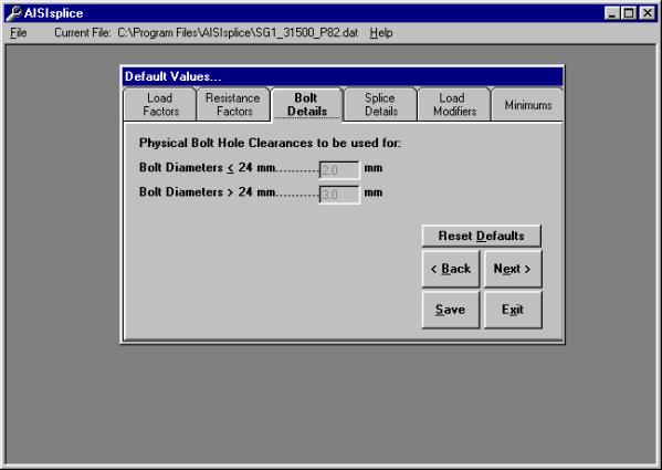
The Bolt Details tab shows
the user the bolt hole clearances used (shown only for the SI units system).
Splice Details Tab:
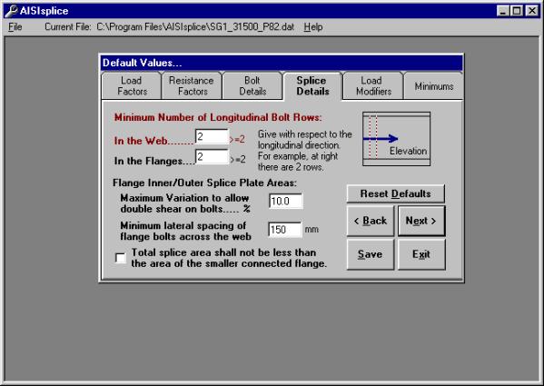
Click
the Splice Details tab to set
minimum limits on the number of required longitudinal flange and web bolt rows
(the software will not accept values less than 2).
In
order to eliminate the effects of eccentric connections, the maximum variation
between the areas of the inner and outer flange splices is limited to 10%, as
specified in AASHTO C6.13.6.1.4c.
However, the user may opt to reduce this percentage to as low as 5%.
The
software uses a default value of 6 in. (150 mm) for the lateral distance
between the flange bolts closest to the web, lying on each side of the
web. This generous value, which can be
altered by the user as needed, is used in the design mode to allow for easy
construction.
Finally,
the default values section allows the user to require the flange splice plates
to have, as a minimum, the area of the smaller connected flange.
Load Modifiers
Tab:
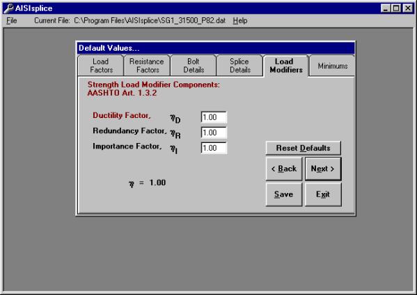
The value for the load modifier is dependent on factors relating to
component and connection ductility, member redundancy, and operational
importance of the bridge. The software
default value for any load modifier is 1.0.
The
factors for ductility, redundancy and importance are determined by the
guidelines set forth in AASHTO 1.3.3, 1.3.4, and 1.3.5, respectively.
Minimums Tab:
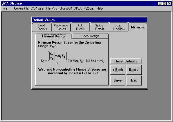
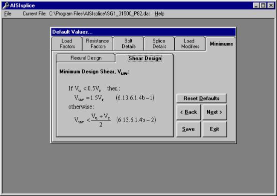
In
order to comply with AASHTO 6.13.6.1.4c and 6.13.6.1.4b, flexural and shear
design minimums should be used to further proportion flange and web design
forces. The software applies flexural
and shear design minimums, with respect to the 1999 Interim to the AASHTO LRFD Specifications.
Flexural
minimums are applied to the girder, referred to as the critical girder, with
the least non-composite moment of inertia of the two adjoined girders. Shear minimums are applied to the girder
having the smaller shear resistance.
The critical girder is used to determine section properties, as well as
design stresses.
Design Report Format
1. PROBLEM
DEFINITION
2. DESIGN LIMIT
STATES
2.1. During Construction
2.2. Fatigue Limit State
2.3. Strength Limit State
2.3.1a For POSITIVE Moment
2.3.1b For NEGATIVE Moment (if applicable)
2.3.2. For Shears
2.3.3. Strength Design Forces
2.4. Service Limit State
2.4.1a For POSITIVE Moment
2.4.1b For NEGATIVE Moment (if applicable)
2.4.2. For Shears
2.4.3. Service Design Forces
3. SUMMARY OF AASHTO
SPLICE DESIGN FORCES
4. SPLICE DESIGN
4.1. Top Flange Splice Design
4.1.1. Plate Design
4.1.2. Bolt Design
4.1.3. Block Shear Rupture Check (if applicable)
4.2.
Bottom Flange Splice Design
4.2.1. Plate Design
4.2.2. Bolt Design
4.2.3. Block Shear Rupture Check (if applicable)
4.3. Web Splice Design
4.3.1. Bolt Design
4.3.2. Plate Design
4.3.3. Block Shear Rupture Check (if applicable)
5. SUMMARY
PERFORMANCE
RATIOS
SPLICE
DIMENSION SUMMARY
FILLER
SUMMARY (if applicable)
Analysis Report Format
I. SPLICE ANALYSIS
SUMMARY
1. Top Flange Splice
2. Bottom Flange Splice
3. Web Splice
1. PROBLEM
DEFINITION
2. DESIGN LIMIT
STATES
2.1. During Construction
2.2. Fatigue Limit State
2.3. Strength Limit State
2.3.1a For POSITIVE Moment
2.3.1b For NEGATIVE Moment (if applicable)
2.3.2. For Shears
2.3.3. Strength Design Forces
2.4. Service Limit State
2.4.1a For POSITIVE Moment
2.4.1b For NEGATIVE Moment (if applicable)
2.4.2. For Shears
2.4.3. Service Design Forces
3. SUMMARY OF AASHTO
SPLICE DESIGN FORCES
4. SPLICE ANALYSIS
4.1. Top Flange Splice Analysis
4.1.1. Plate Analysis
4.1.2. Bolt Analysis
4.1.3. Spacing Limit Analysis
4.1.4. Block Shear Rupture Analysis (if applicable)
4.2. Bottom Flange Splice Analysis
4.2.1. Plate Analysis
4.2.2. Bolt Analysis
4.2.3. Spacing Limit Analysis
4.2.4. Block Shear Rupture Analysis (if applicable)
4.3. Web Splice Analysis
4.3.1. Bolt Analysis
4.3.2. Plate Analysis
4.3.3. Spacing Limit Analysis
4.3.4. Block Shear Rupture Analysis (if applicable)
5. SUMMARY
PERFORMANCE
RATIOS
FILLER
SUMMARY (if applicable)
AISIsplice
designs and analyzes bolted steel girder splices. Designs are limited to three splice plates for each connected
flange and two splice plates for the web connection. Analyses must have two web connection splice plates of the same
thickness, and one or three flange splice plates, per flange. Splices must be symmetric about the gap
centerline for any given component (i.e. the top flange left girder section of
the splice is identical to the top flange right girder section). Web splices are centered about the center of
the web.
The
software is limited to splices of straight, right, homogeneous, steel I-girders
of which the top flange is not embedded in the concrete slab, the flanges are
parallel, and are not skewed at the location of the splice. Adequate clearance must be provided between
splice plates and fillets of rolled beams or welds of plate girders. Bolt patterns are limited to constant pitch,
non-staggered bolt patterns.
When
thick flange fillers are used, it may be necessary to increase the number of
bolts required to develop or extend the filler as per AASHTO 6.13.6.1.5. Therefore, it is possible that the number of
flange bolts required on one side of the centerline is greater than the number
required on the other side. Because
this software is limited to symmetric splice designs, the larger number of
required bolts is used for both sides of the gap. It is recommended that the user use a non-symmetric
cost-effective splice. However, the
user is cautioned that the lesser number of bolts does not necessarily satisfy
all other design criteria (i.e. slip resistance, bearing resistance, block
shear rupture, etc.) and, therefore, must be checked.
1.
American
Association of State Highway and Transportation Officials, “LRFD Bridge Design
Specifications,” 1999 Interim, Washington, DC, 1999.
2.
American
Association of State Highway and Transportation Officials, “LRFD Bridge Design
Specifications,” Second Edition, Washington, DC, 1998.
3.
American
Institute of Steel Construction, “AISC
Database Version 2.0,” Metric and English Units, Chicago, IL, 1994.
4.
American
Institute of Steel Construction, “LRFD
Manual of Steel Construction,” Volumes I and II, Chicago, IL, 1994.
5.
Sheikh-Ibrahim,
Firas I., and Frank, Karl H., "The
Ultimate Strength of Symmetric Beam Bolted Splices," AISC Engineering
Journal, Third Quarter, 1998, pp.106-118.
6.
Sheikh-Ibrahim,
Firas I., and Frank, Karl H., "The
Ultimate Strength of Unsymmetric Beam Bolted Splices," AISC
Engineering Journal, Second Quarter, 2001, in-print.
7.
Sheikh-Ibrahim,
Firas I., and Frank, Karl H., "Bolted
Field Splices for Steel Bridges," ASCE Proceedings of Structures Congress
XIV, Volume 1, Chicago, IL, April 1996, pp.290-297.
1.
Bridge Name: PTC Bridge B438, Somerset
County, Pennsylvania
Project Type: Bridge Replacement/New Construction
Bridge Type: Composite Slab-on-I Steel Girder Bridge
Number of Girders: 5
Girder Spacing: 2.7 m
Skew Angle: 45.00 Degrees
Span Type: Simple Span
Span Length: 56.40 m
Splice Location: 14.52 m
Design Specifications: 1999 AASHTO LRFD + 1996 PennDOT DM4
Owner:
Pennsylvania Turnpike Commission
Design Firm: HDR Engineering, Inc.- Pittsburgh
Splice Designer: Jason A. Fuller, P.E.
Designer Quote: “The amount of man-hours saved
by using AISIsplice was incredible, but in addition to that, the aggravation of
redoing a splice over and over again by hand to make it efficient and cost
effective was eliminated. Once we had a
viable solution by the program, it was verified by hand and the program was
dead on.”
2.
Bridge Name: Rocky Hollow Bridge,
Somerset County, West Virginia
Project Type: Bridge Rehabilitation
Bridge Type: Composite Slab-on-Steel Rolled Beam Girder Bridge
Number of Girders: 4 (dual structures)
Girder Spacing: 9’-0”
Skew Angle: »16.00 Degrees
Span Type: 4 Continuous Spans
Span Length: 40 ft – 56 ft – 84 ft – 62 ft
Splice Location: 16 ft back from Pier 2, 18 ft back from Pier 3
Design Specifications: 1999 AASHTO LRFD
Owner:
West Virginia Department of Transportation – Division of Highways
Design Firm: HDR Engineering, Inc.- Pittsburgh
Splice Designer: Jason A. Fuller, P.E.
Designer Quote: “AISIsplice simplified the
checking of the existing splices and the design of a continuity splice. Once all the input values were calculated,
which would be required to do for hand calculations also, it took minutes to
run the program instead of hours to do the calculations.”
3.
Bridge Name: PTC Bridge B481, Somerset
County, Pennsylvania
Project Type: Bridge Replacement/New Construction
Bridge Type: Composite Slab-on-I Steel Girder Bridge
Number of Girders: 5
Girder Spacing: 2.7 m
Skew Angle: 69.52 Degrees
Span Type: 2 Continuous Spans
Span Length: 49.16 m - 49.16 m
Splice Location: 31.5 m, 66.8 m
Design Specifications: 1999 AASHTO LRFD + 1996 PennDOT DM4
Owner:
Pennsylvania Turnpike Commission
Design Firm: HDR Engineering, Inc.- Pittsburgh
Splice Designer: Firas I. Sheikh-Ibrahim, Ph.D.
Designer Quote: “I received numerous positive
feedback, but I did not appreciate AISIsplice until I had to use it to design
the splices for PTC Bridge B481.
AISIsplice produced cost-effective splices in a relatively short
time. The use of AISIsplice helped cut
the cost of materials and design man-hours.”
4.
Bridge Name:
Project Type:
Bridge Type:
Number of Girders:
Girder Spacing:
Skew Angle:
Span Type:
Span Length:
Splice Location:
Design Specifications:
Owner:
Design Firm:
Splice Designer:
Designer Quote:
If you would like to be included in future
AISIsplice publications, please fill in the items above and email them to AISI.